![[Julio Vega's home page]](https://gsyc.urjc.es/jmvega/figs/cabecera.jpg "Julio Vega's home page")
Table of contents
- 2009.12.16. Algorithm detect and pay attention to faces and parallelograms
- 2009.11.26. Running with noise
- 2009.11.25. Parallelograms reconstruction
- 2009.11.24. Corridor clearer reconstruction
- 2009.11.20. Corridor corner reconstruction
- 2009.11.19. Corridor reconstruction
- 2009.11.11. Whole floor reconstruction using single segments
- 2009.11.10. First segment merge implementation
- 2009.11.02. Floor 3D reconstruction using lines
- 2009.10.28. Complete floor 3D reconstruction
- 2009.10.28. Camera extrinsic parameters manual adjustments
- 2009.10.22. Step by step camera extrinsics and intrinsics measurements
- 2009.10.09. Problem: pantilt oscillations
- 2009.10.08. [Bonus track] Pioneer Vs. Nao
- 2009.10.08. 3D Floor reconstruction with camera autocalibration
- 2009.10.02. Star Trek National Convention. Talk about Robotics
- 2009.10.02. Systematic floor reconstruction
- 2009.09.14. Systematic search
- 2009.09.09. Following faces around scene, with saliency and liveliness dynamics
- 2009.09.03. Following faces around scene
- 2009.08.31. Following multiple faces from different scene perspectives
- 2009.08.25. Following multiple faces
- 2009.08.19. Following one face
- 2009.07.17. Improving local navigation algorithms
- 2009.06.16. Floor 3D recognition using monocular vision from robot camera
- 2009.06.02. Virtual Reality Master Project: how to enhance virtual reality with 3D sound
- 2009.05.20. Pioneer's running between two lines, like a road
- 2009.05.10. JDE Seminar: how to compile, link and debug our C applications on Linux
- 2009.05.05. Skinning, muscles, skeleton, clothes, and dynamics techniques modeled under Maya
- 2009.04.28. VFF over visual information
- 2009.04.12. San Teleco Talk about Robotics
- 2009.04.02. Instantaneous GPP calculation
- 2009.03.30. GlobalNavigation schema draws planned route
- 2009.03.29. GlobalNavigation schema with Gazebo simulator
- 2009.03.28. First stable GlobalNavigation schema
- 2009.03.27. Border points detected with OpenCV
- 2009.03.27. Frontier points detected with OpenCV
- 2009.03.24. Frontera schema using OpenCV
- 2009.03.20. Frontera schema testing
- 2009.03.20. Frontera schema includes the virtual Pioneer
- 2009.03.10. Frontera schema under GTK
- 2009.02.24. Frontera schema under GTK
- 2009.02.17. Frontier hypothesis for floor 3D recognition
- 2009.02.10. Color filtering for frontier hypothesis, from lab ceiling cameras
- 2009.02.03. Floor 3D recognition using monocular vision from robot camera
- 2009.01.23. Perlin Noise
- 2009.01.15. Modeled and animated human skeleton
- 2009.01.12. Wandering
- 2009.01.08. Classic pong modeled and animated under Maya
2009.12.16. Algorithm detect and pay attention to faces and parallelograms
In this interesting video, we can see how our system reconstruct and follow detected faces and parallelograms. Now, we've only a set of attention system elements (parallelograms and faces) with saliency and liveliness dynamic. Both of them has a centroid point used to focus image towards them.
2009.11.26. Running with noise
Here, we can see the application behavior with too much noise. We've tried the parallelogram recognition with a very low line detection Hough Transform threshold, in order to show the robustness of our algorithm.
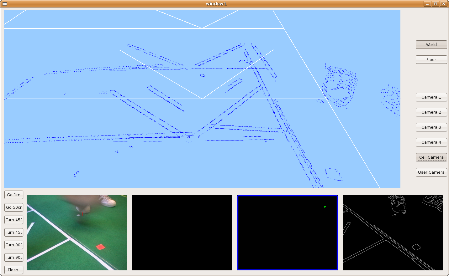
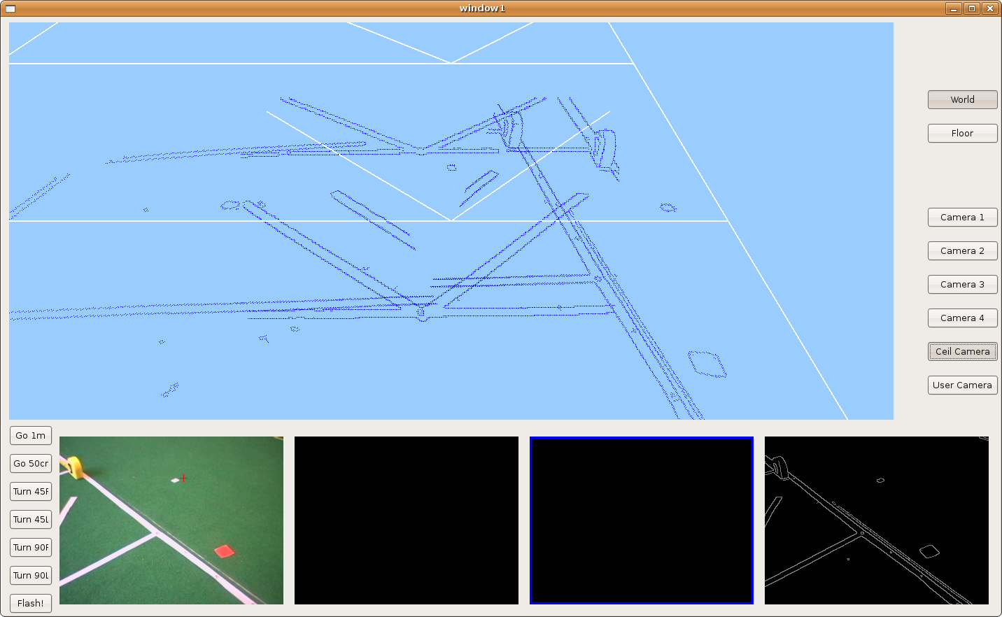
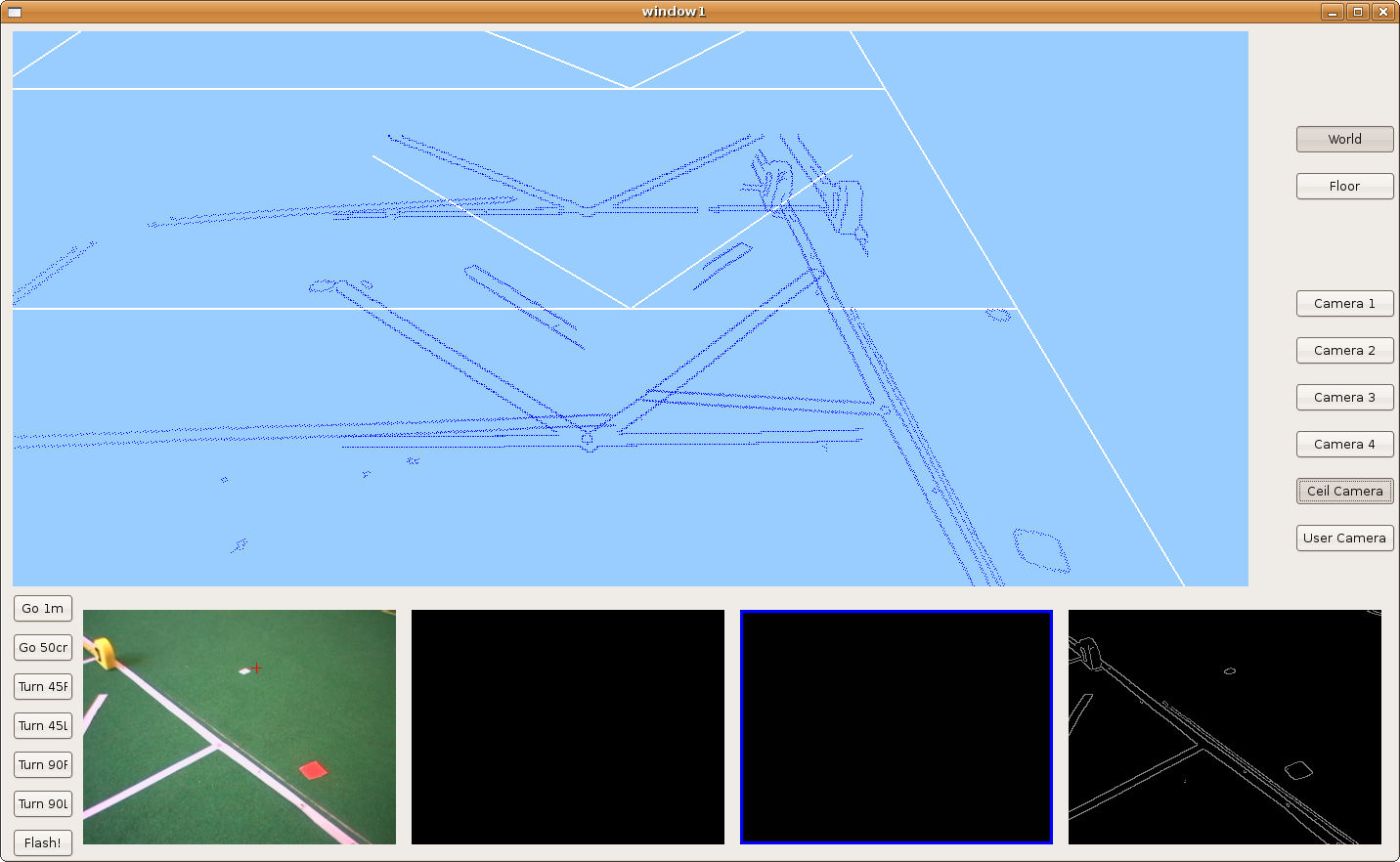
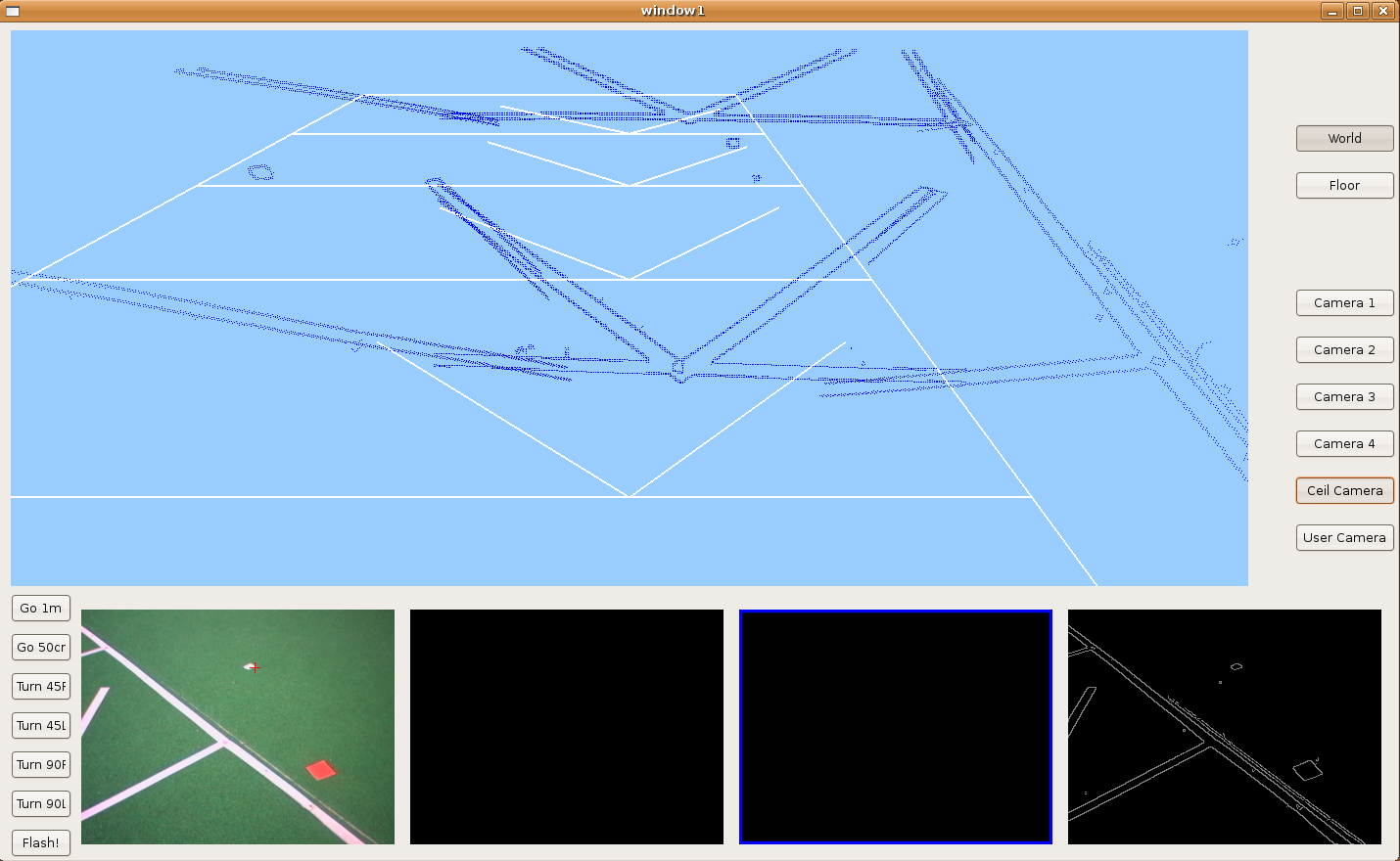
2009.11.25. Parallelograms reconstruction
We introduce the hypothesize concept in order to detect partial-seen parallelograms and reconstruct them. Here we can see lots of parallelograms over the floor and how the robot is able to detect and reconstruct some of them.
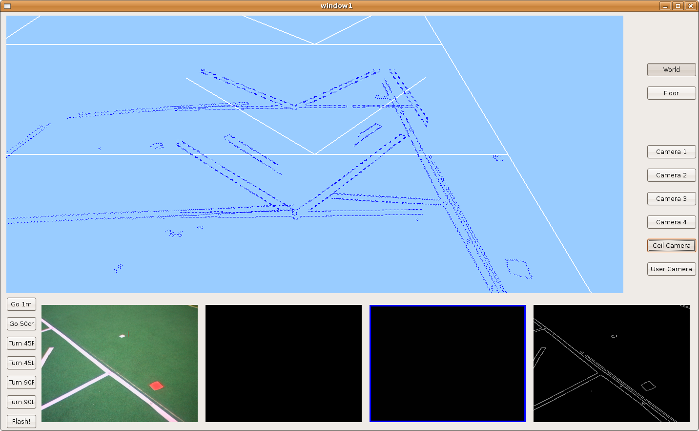
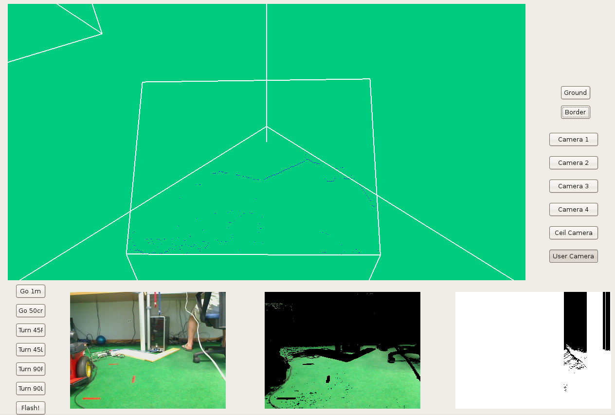
2009.11.24. Corridor clearer reconstruction
Now, we can see a clearer corridor reconstruction. We've only a single line with each side of the corridor. The horizontal lines belong with corridor doors.
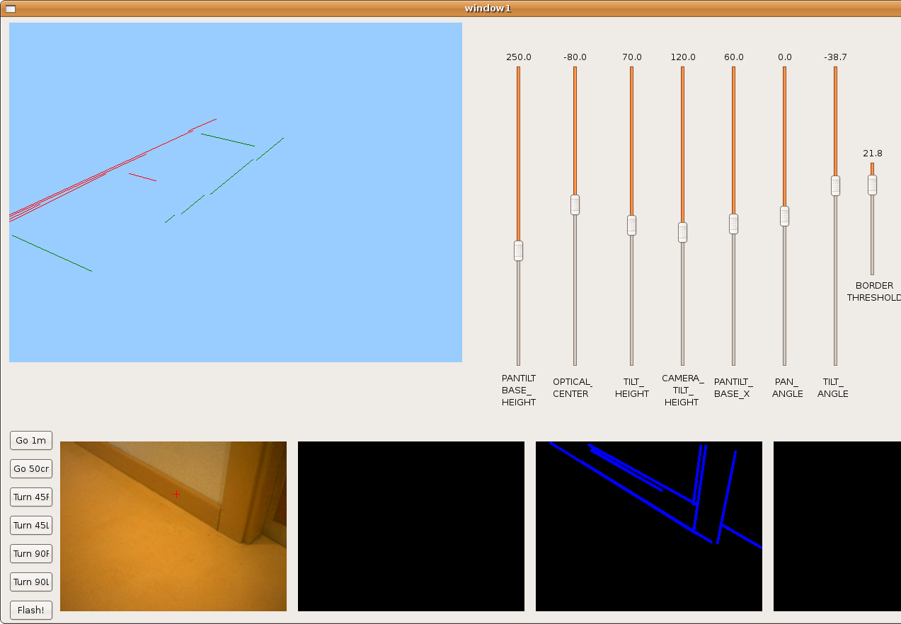
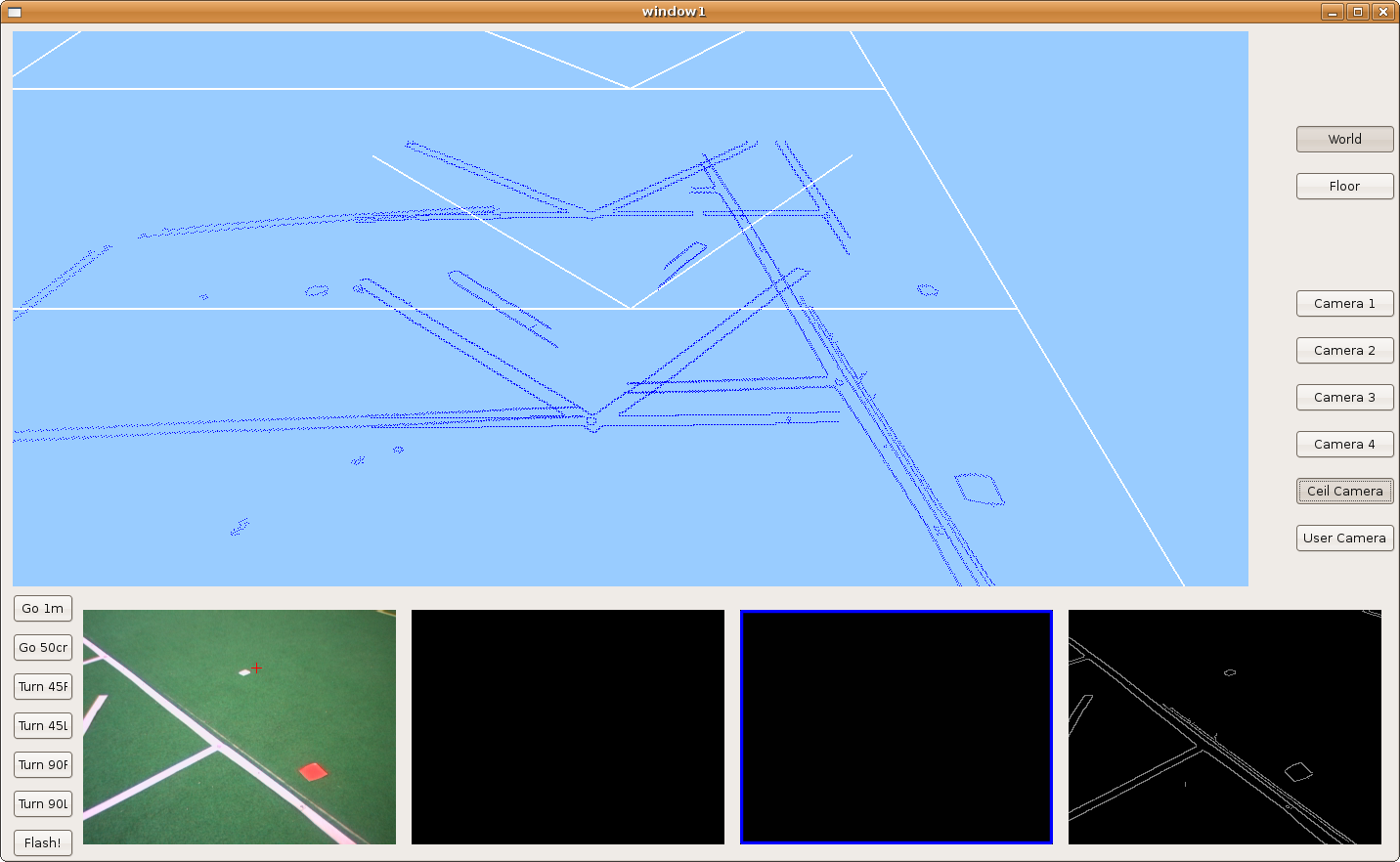
2009.11.20. Corridor corner reconstruction
One more step. Today, Pioneer goes through the corridor with free rotational movement in order to reconstruct when it's turning around corner.
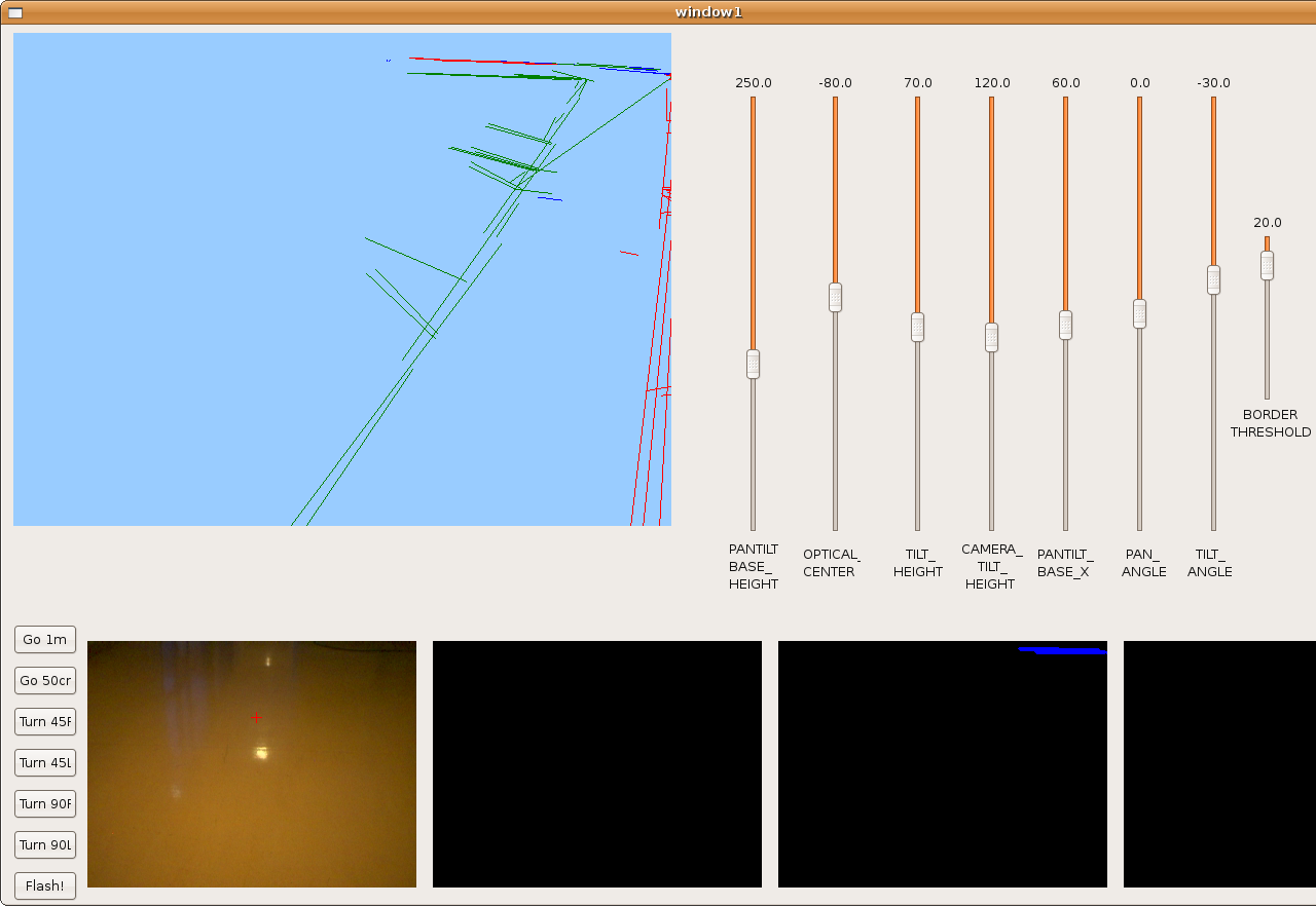
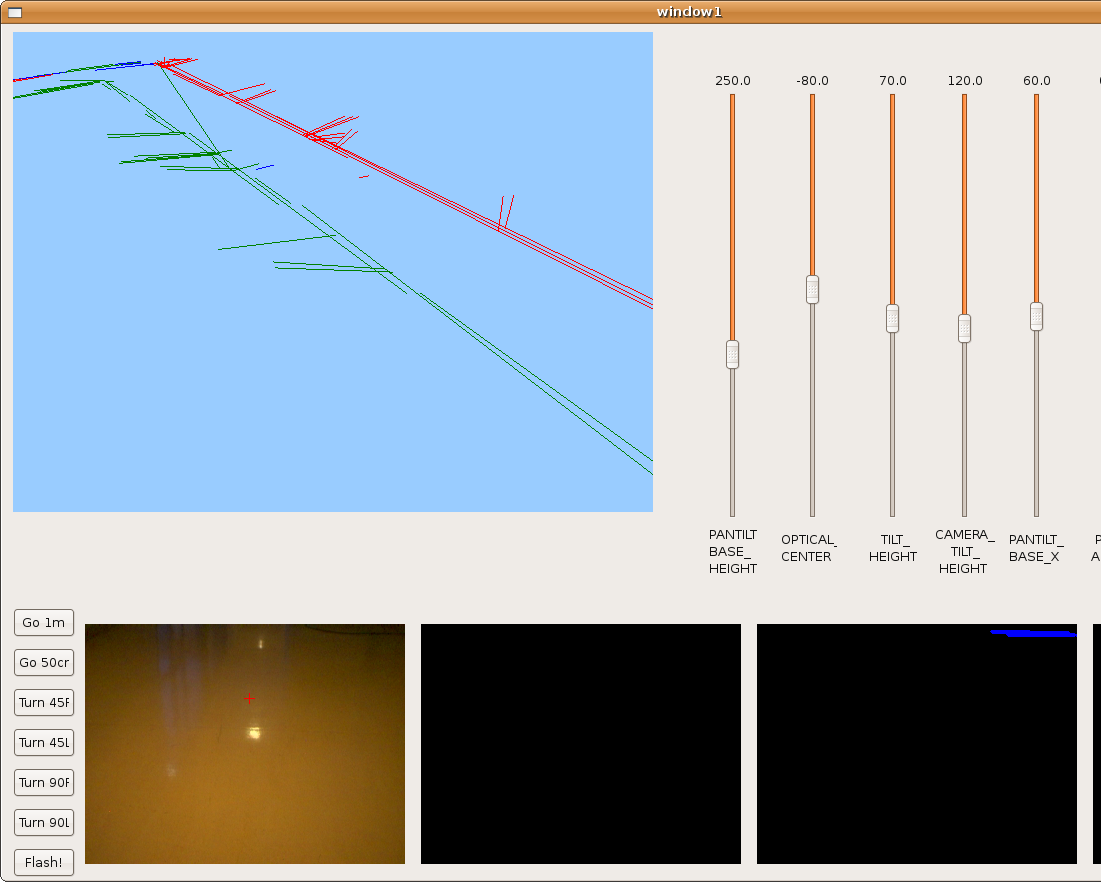
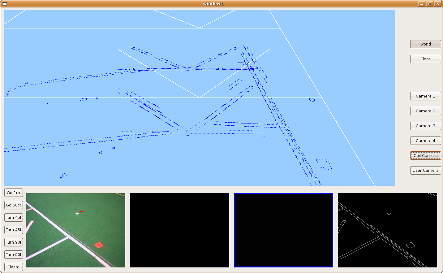
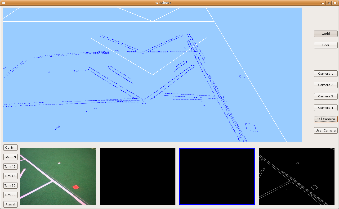
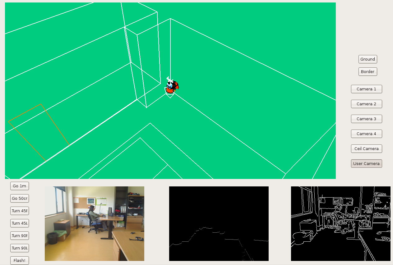
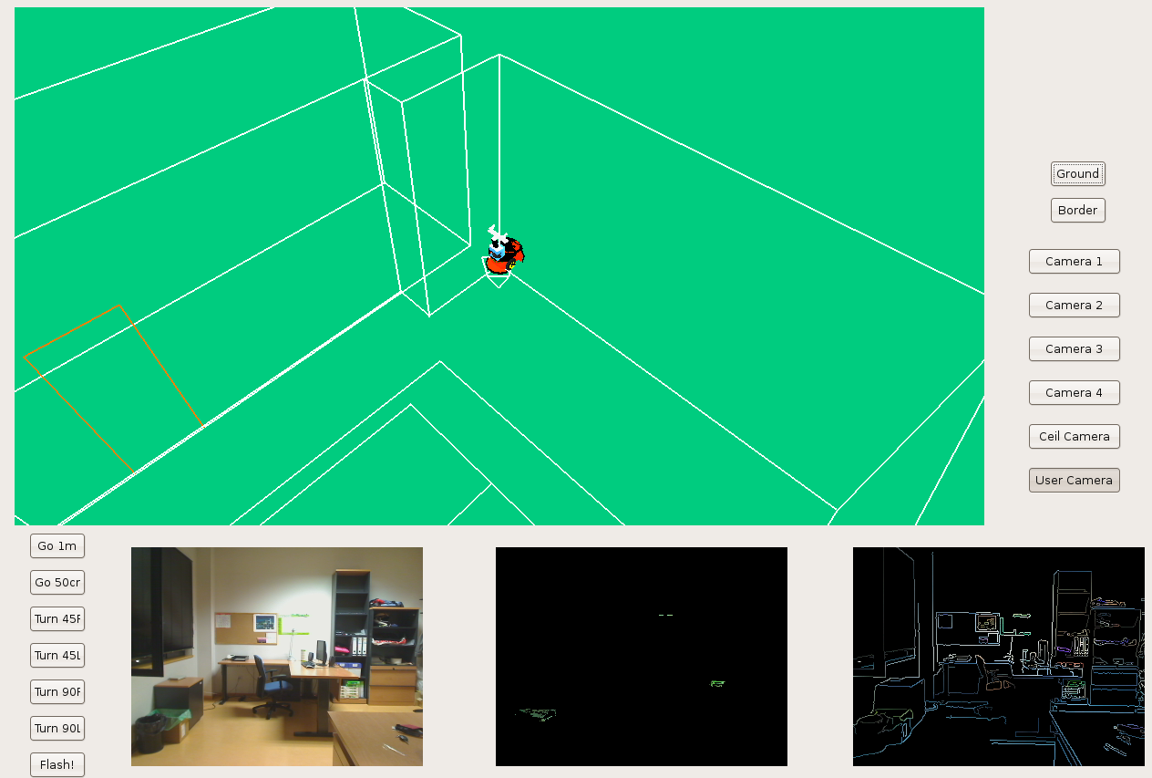
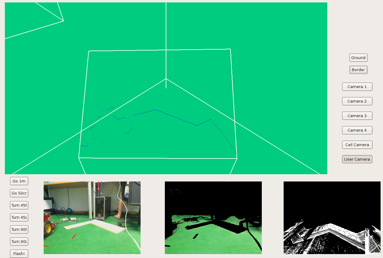
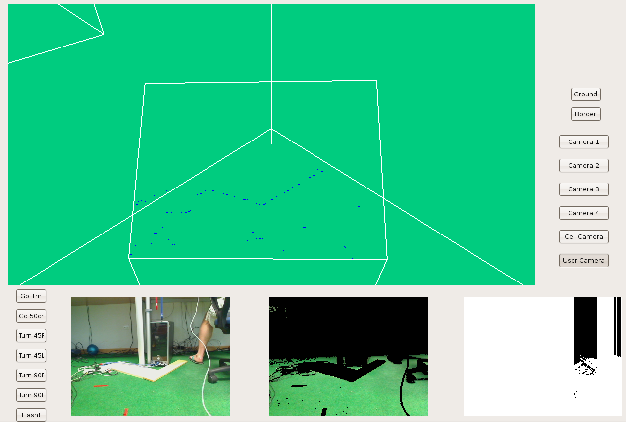
2009.11.19. Corridor reconstruction
Using last development, Pioneer is able to reconstruct the department corridor. The main difficult is in the reflections over floor, so we've modulated correctly many filter parameters in order to avoid them. We can see the result in the next two images.
2009.11.11. Whole floor reconstruction using single segments
Here we've improved the merge function in order to get the longest segment for every direction in the world. And robot's able to get the whole floor 3D reconstruction using single lines.
2009.11.10. First segment merge implementation
At this point, we've converted our world to segments. Furthermore, we want to merge and overlap repeated lines. The first implementation is a good step because we have:
- Single and not repeated segments in the world.
- We check parallel segments and we keep the segment memory correctly.
The result is the next. Now we want to improve the merge function in order to get the longest segment for every direction in the world.
2009.11.02. Floor 3D reconstruction using lines
Before we've been using points to represent the floor lines. Now, In order to decrease the time to process image, we want to work with lines. So we've segmented the image detected borders and we obtain a set of lines drawn by the OpenGL instruction GL_LINES.
2009.10.28. Complete floor 3D reconstruction
Using the last development, I've added robot Pioneer movement in order to reconstruct the whole floor.
On the next videos we can see:
- 1 The distance covered by the robot.
- 2 The 3D floor reconstruction on its virtual 3D-memory.
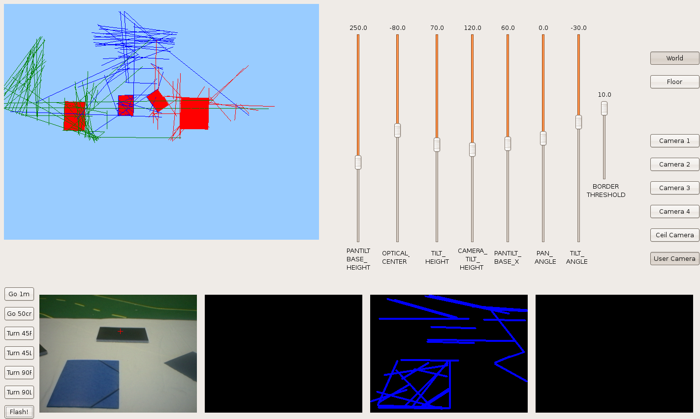
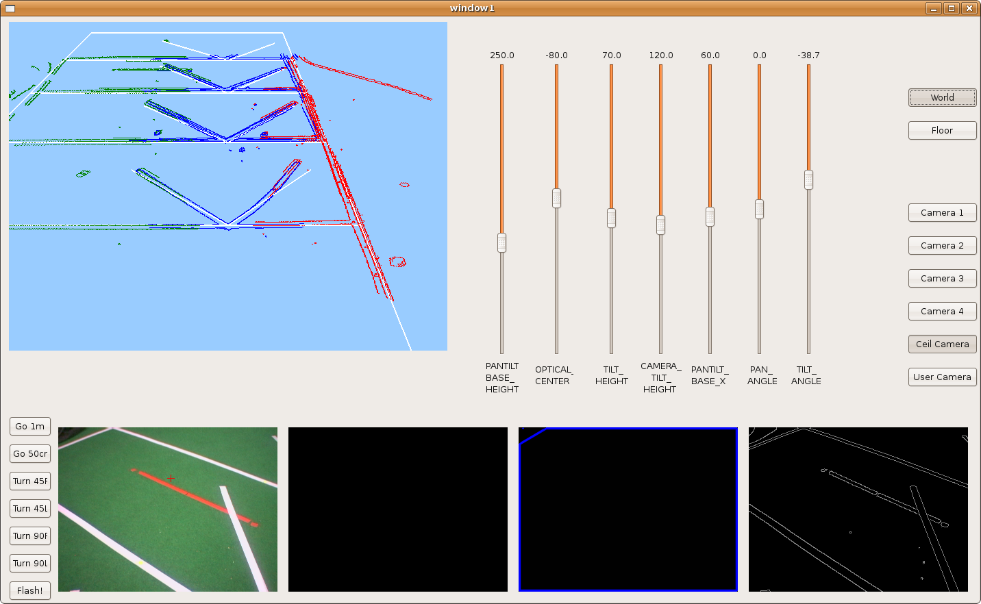
2009.10.28. Camera extrinsic parameters manual adjustments
Because of last not-perfect results, I've added new sliders on the frontera GUI; that way, I've manually adjusted camera extrinsic parameters and now the result is perfect.
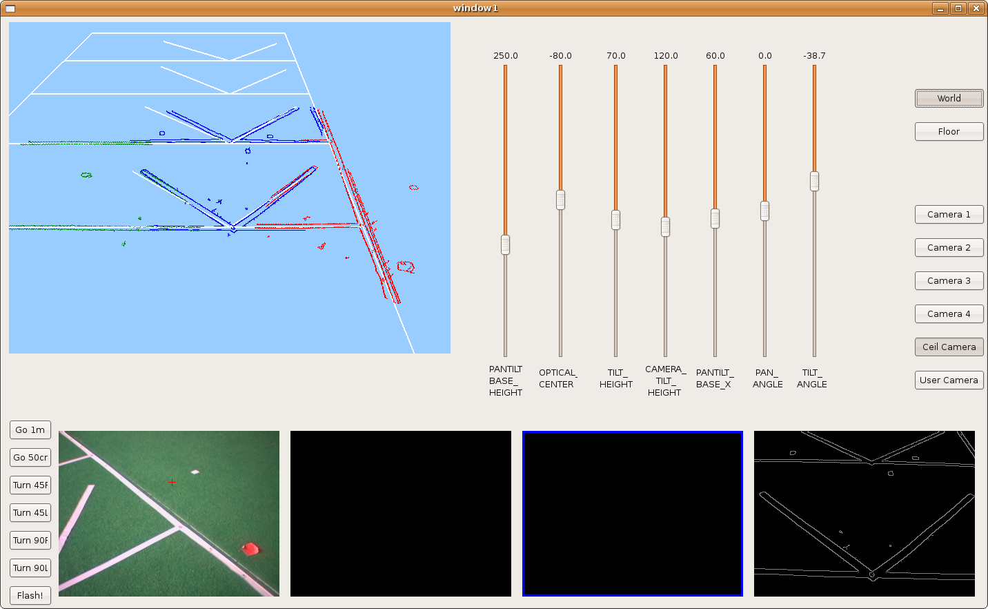
We can see the correlations between the three points of view, each of them is painted with a different color.
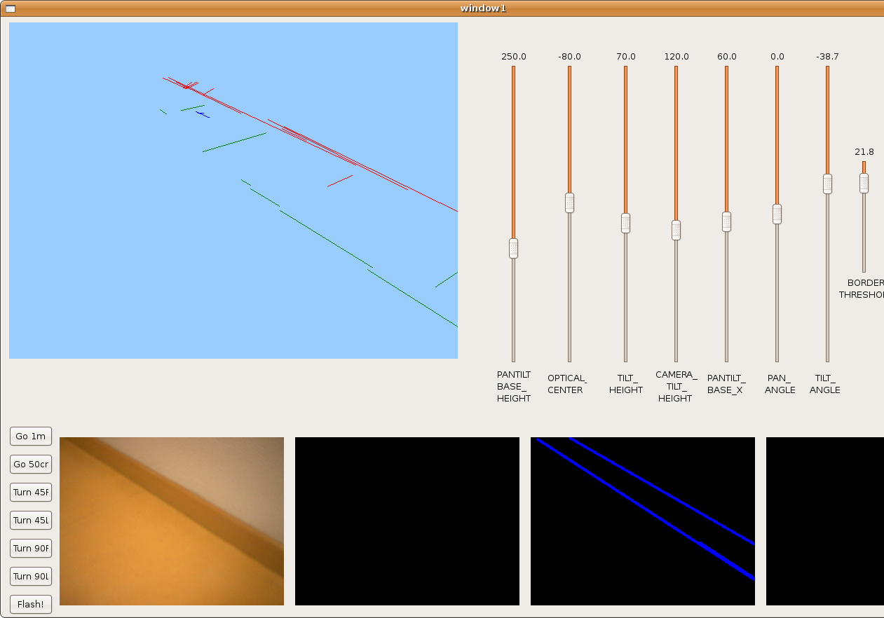
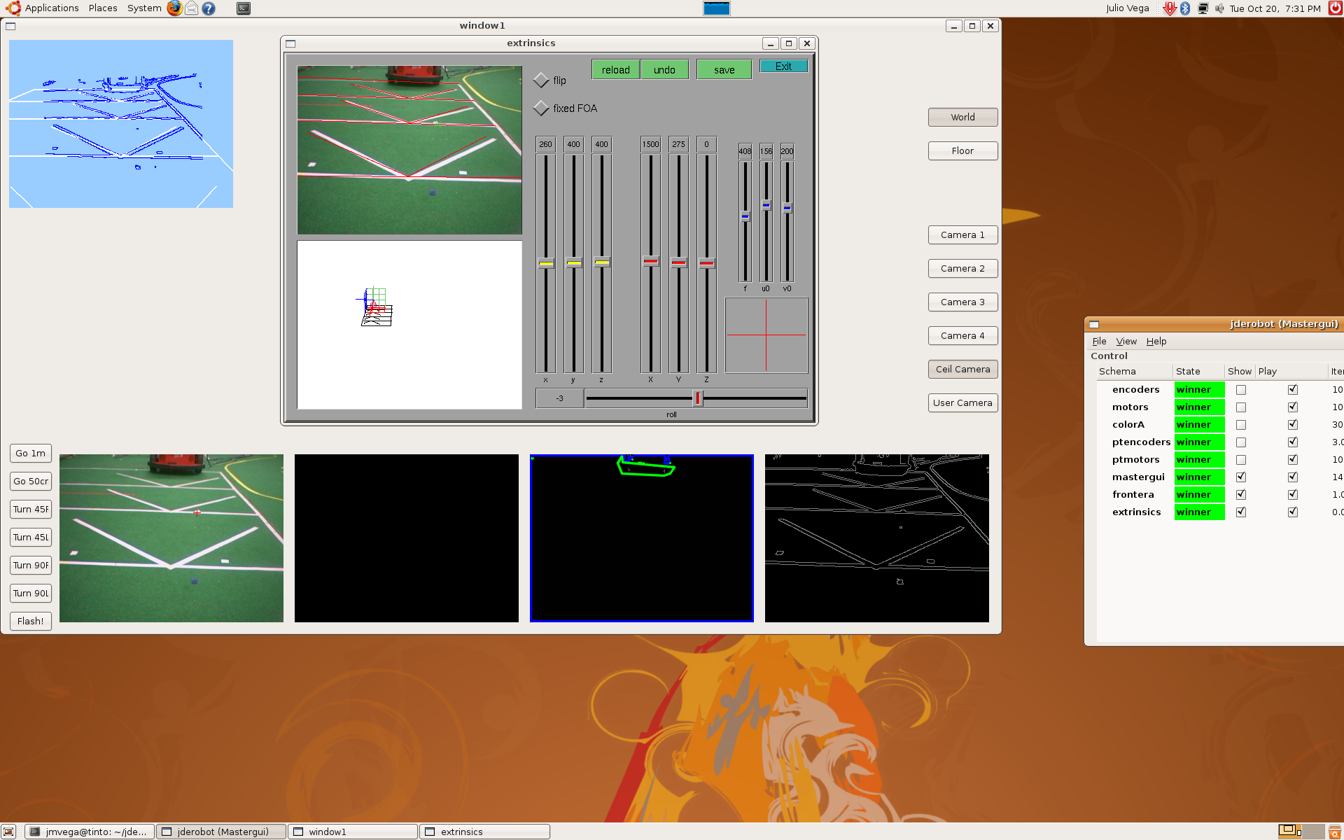
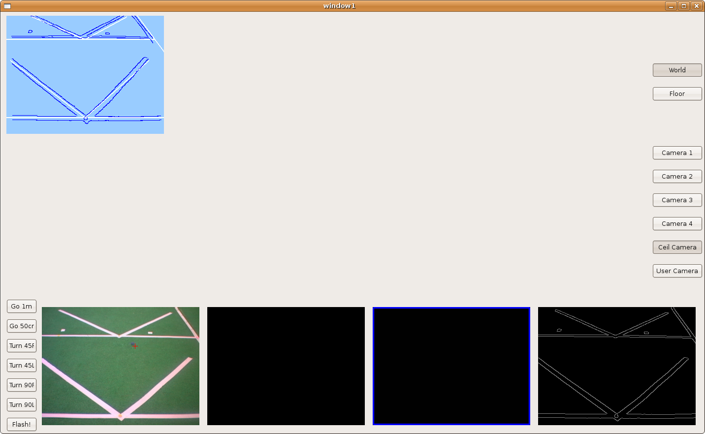
2009.10.22. Step by step camera extrinsics and intrinsics measurements
As I said last time, we'd several problems with pantilt oscillations. Furthermore, deep estimations weren't very precise. So, we decided to extract camera extrinsics and intrinsics parameters, step by step.
1) Using extrinsics schema, and knowing the camera absolute position in the world, we determined the correct camera intrinsics parameters (u0, v0 and roll). At this moment, we realized about progeo coordinate system more info. Definitely, we use a different one.
This is the result:
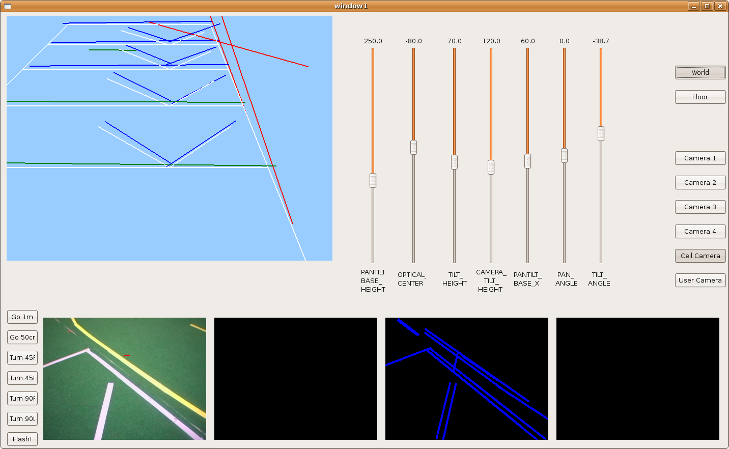
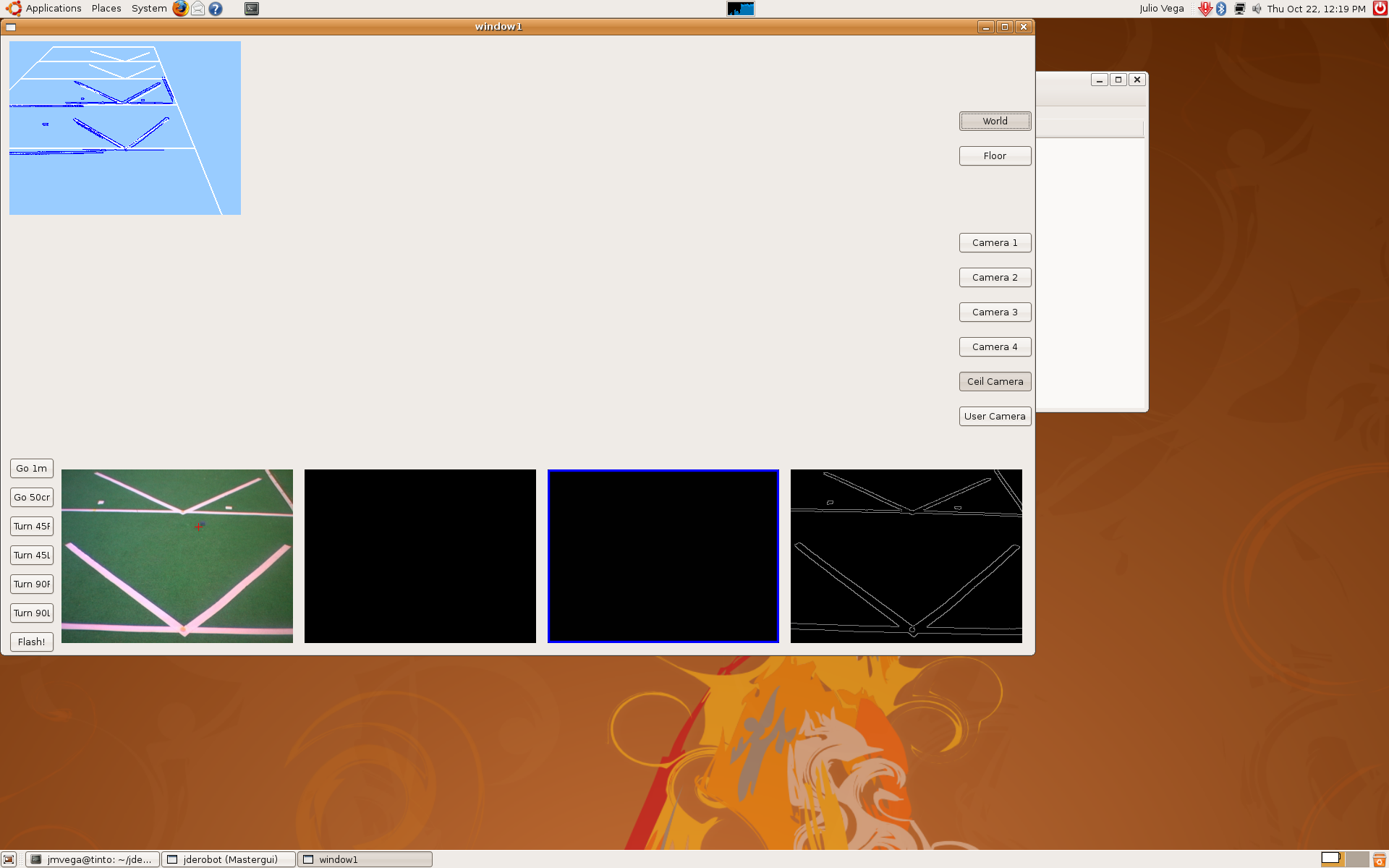
2) After that, we put the camera above the pantilt device, we measured its position again, and this is the result.

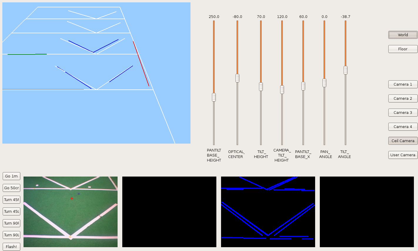
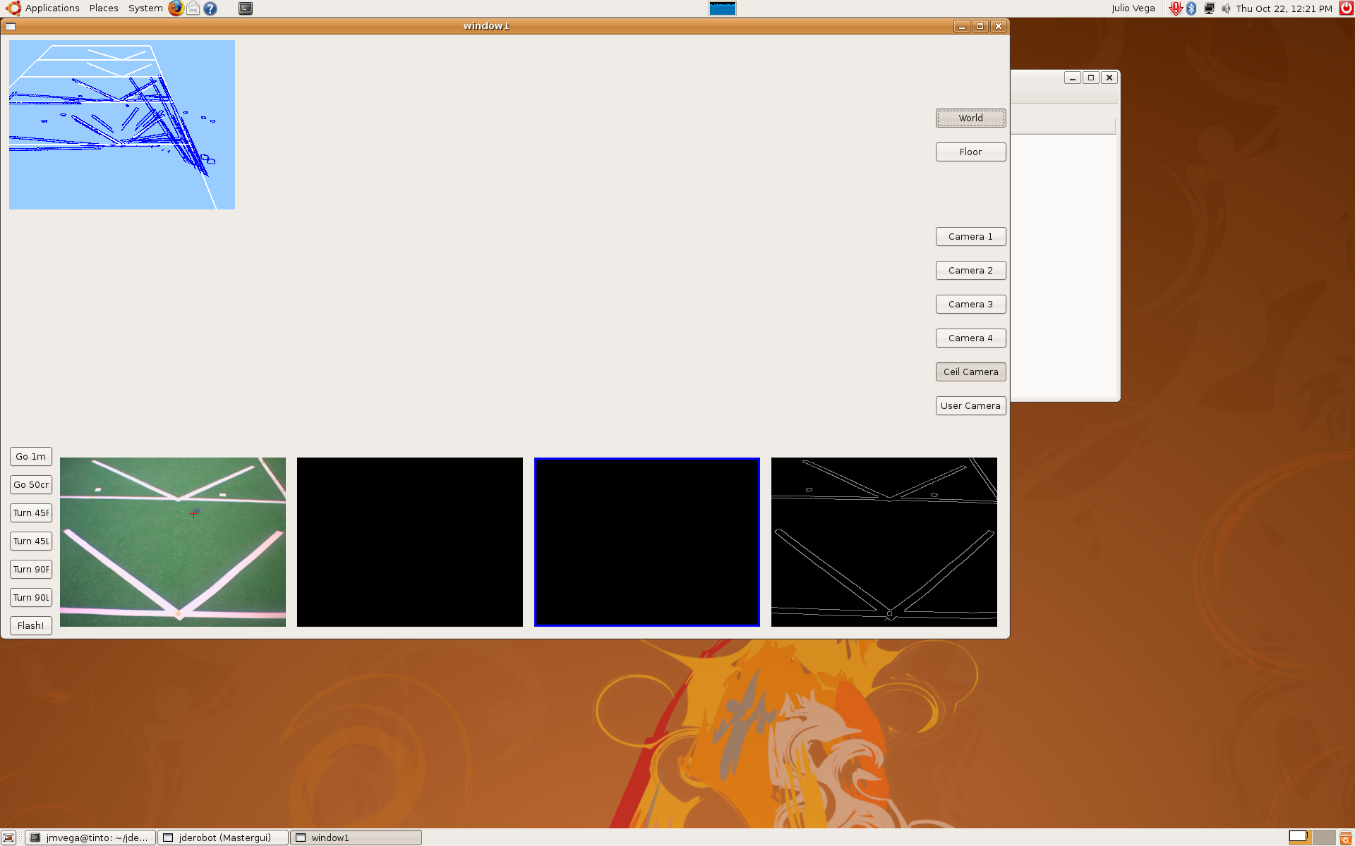
3) The third step was to use mathematical model, but only with a single RT matrix. We'd to correct pantilt position, the optical center and the tilt angle given by the pantilt encoders... we did that again and again until we got this result.
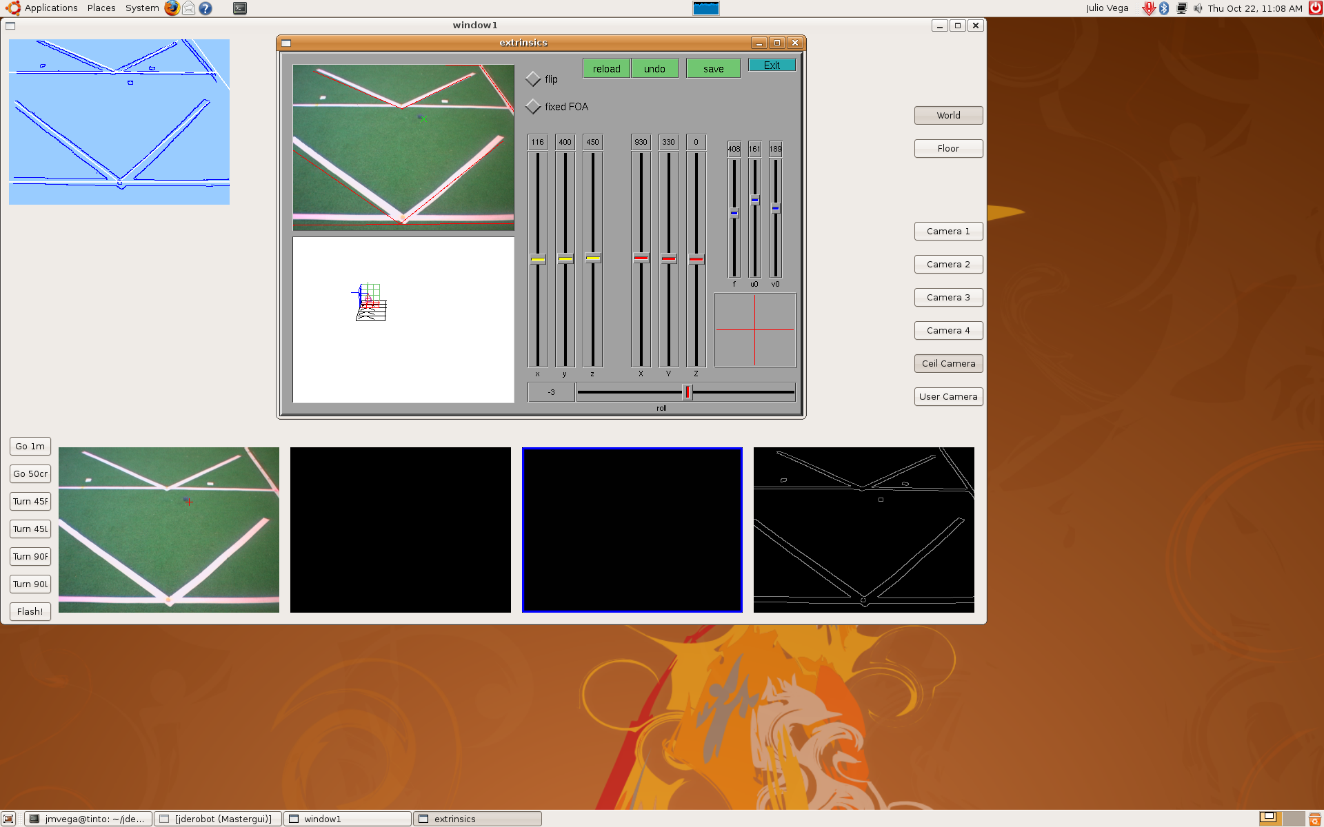
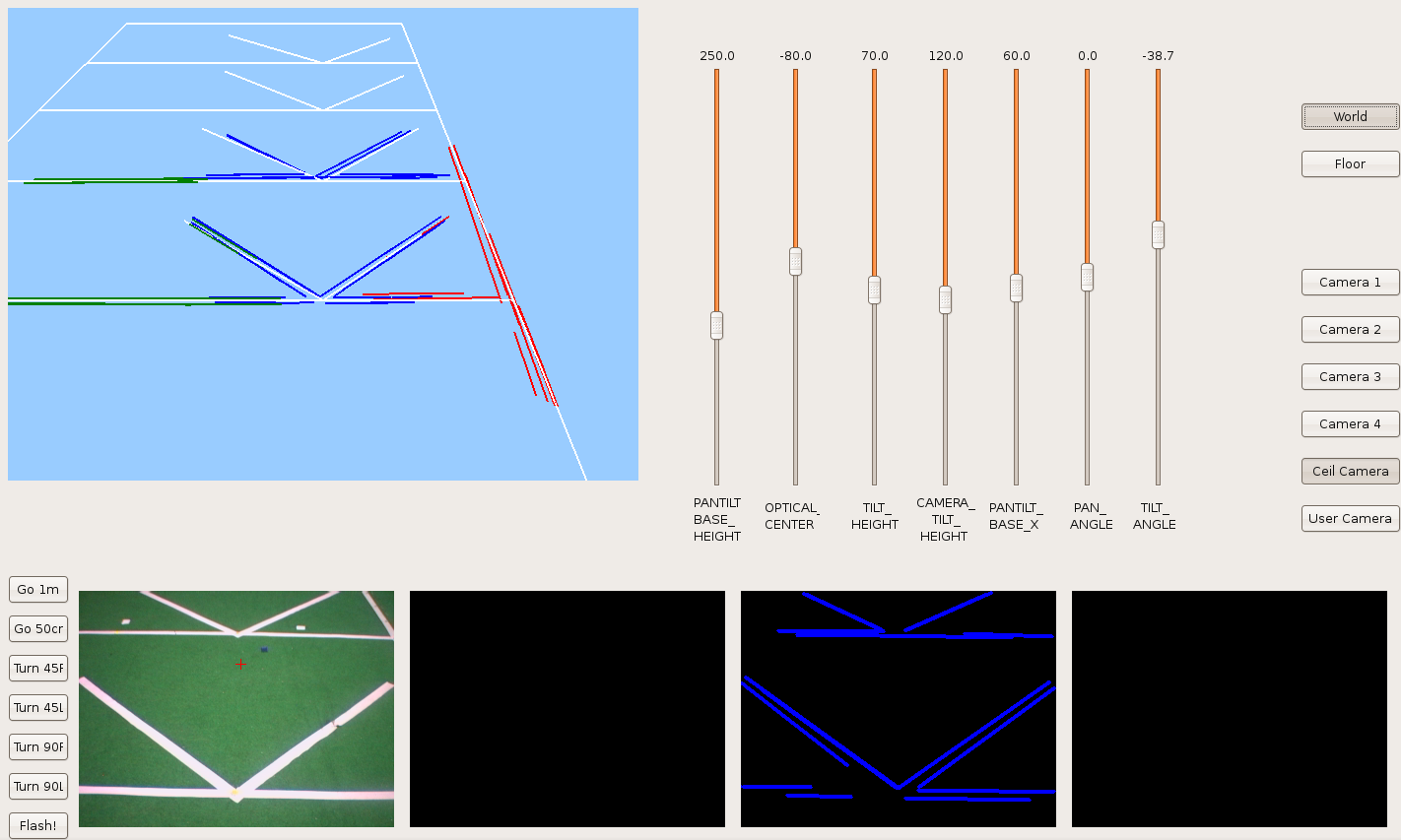
4) When we knew every parameter (PANTILT_BASE_HEIGHT, ISIGHT_OPTICAL_CENTER, TILT_HEIGHT, CAMERA_TILT_HEIGHT, PANTILT_BASE_X, PANTILT_BASE_Y) we continued with the rest of RT matrix's until we'd the whole system. This is the result.
5) Finally, in order to check the correct mathematical model, we moved pantilt with saccadic movements and we're able to check the pantilt oscillations problem that I told last time. We got these sequences.


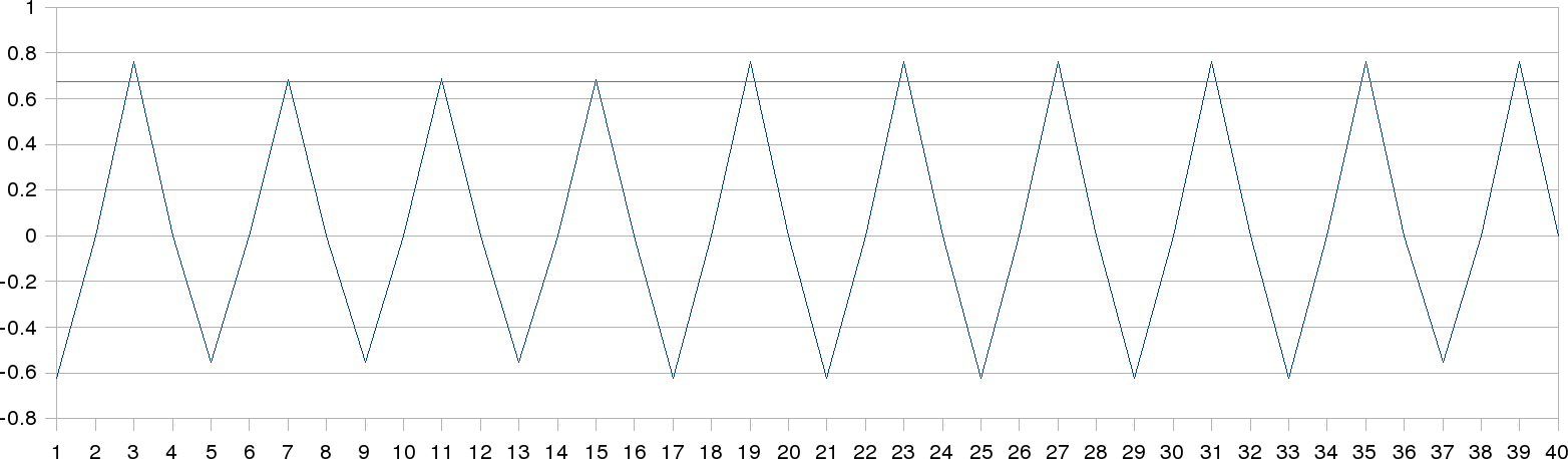
2009.10.09. Problem: pantilt oscillations
We've realized that pantilt movements are not uniform. Each iteration, the pantilt is not on the same position as last iteration. On this figure, we can see the oscillations on pan axis (blue line) when it's moving forward left and right sides; the final adopted positions are different. On the other hand, the tilt axis (red line) isn't moving, so the position is always the same. The values are expressed on radians.
2009.10.08. [Bonus track] Pioneer Vs. Nao
2009.10.08. 3D Floor reconstruction with camera autocalibration
Now, we've introduce the RT matrix concept in order to calculate relative positions. So, we can know the camera position in the world and its focus of attention (foa). We have the following RT-matrices:
- Robot position relative to world coordinates (translation on X & Y axis and rotation around Z axis)
- Pantilt base position relative to robot position (translation on Z axis)
- Tilt height position relative to pantilt base (translation on Z axis and rotation around Z axis)
- Tilt axis relative to tilt height (rotation around Y axis)
- Camera optical center (translation on X & Z axis)
- Focus of attention relative to camera position (translations on X axis)
Because of we don't know specifically where is the optical center on the Isight camera (about 100mm long size), I've test several positions in order to get the best match between real and virtual coordinates. The following images corresponds to different optical centers: -10, -20, -30, -40, -50, -60, -70, -80 and -90 mm from image plane until the bottom of the physical camera.
Finally, we can conclude the best optical center estimation is in the -20 mm position.
-10 mm
-20 mm
-30 mm
-40 mm

-50 mm
-60 mm

-70 mm
-80 mm
-90 mm
2009.10.02. Star Trek National Convention. Talk about Robotics
On the occasion of the Star Trek National Convention, celebrated in Fuenlabrada (Madrid), I've given a talk about the most current real robots and their main components. Nowadays we can see lots of robots whose applications are very diverse.
The slides I've used can be found here.
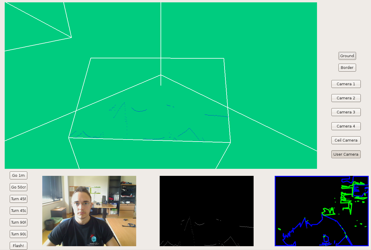
2009.10.02. Systematic floor reconstruction
Here, we can see the three-views floor reconstruction. In this case, we've established three marks manually corresponding to the three different focus of attention (foa). That way, we can recalibrate camera for this three positions.
2009.09.14. Systematic search
On this video, we've tested the systematic search around scene, in order to guarantee system will explore all scene around it. Thus, we'll search faces using random search with systematic search. Now, we're sure that any face will be out of range.
2009.09.09. Following faces around scene, with saliency and liveliness dynamics
Here, we can see a visual attention mechanism. Now, our algorithm chooses the next fixation point in order to track several objects around the robot simultaneously. This behavior is based on two related measurements, liveliness and saliency. The attention is shared among detected faces and new exploration points, when forced time to explore scene is out. Moreover, this time is depends on how many faces are detected. If we've several detected faces, this time will be large...
2009.09.03. Following faces around scene
Now, as we told last time, we have a continuous space in order to gaze the pan-tilt unit according to the major saliency object. Sometimes, we'll have to introduce some virtual faces to explore new zones... And when we find a face, we stop there watching it. Next step is instead of stopping, following that face...
2009.08.31. Following multiple faces from different scene perspectives
Here, you're the last version of this "intelligent followface". We've decided to change our point of view and now instead of having three parts on the scene, we'll have a continuous space in order to gaze the pan-tilt unit according to the major saliency object. Sometimes, we'll have to introduce some virtual faces to explore new zones...
2009.08.25. Following multiple faces
2009.08.19. Following one face
2009.07.17. Improving local navigation algorithms
We're trying three algorithms to solve the problem of local navigation:
VFF
This model is to create a Virtual Force Field with forces that represent: the objets, the destiny and a force that is the resultant of both multiplied with two modulation's parameters.
In our implementation we defined the atraction force (this force represent the destiny) with constant module, and the repulsive force (wich represent the object) with a variable module grow when the robot approaching an object. We get the resultant force solving this equation:
Fresult = a*Fatrac+b*Frepuls
In the equation, a and b are the modulation's parameters and we give their values ad-hoc to make a realistic force field. The image is an example of a virtual force field:
We also have implement a security window to make this algorithm more secure consist in calculate if there is a free zone in front of the robot and if exists we can move the robot with maximum speed. To improve the movements, we use fuzzy logic to do it more fluid. This two improvements give us betters movements.
This video shows this algorithm in progress:
Deliberative
In this type of navigation the robot walk over a line. This line is defined by two points of the way and the robot must be in this line by all the way, if the robot is out of the line it will returns to the line before move.
The next video is the deliberative algorithm running:
so
Hybrid
In the hybrid method we use the implementation of VFF and with destiny a point of the deliberative's way. With this we defined a virtual force field arround all the way and the robot moves by the way avoiding the objects.
In the hybrid navigation as in VFF, we also use fuzzy logic to get fluids movements in the robot.
In the video you can see a simulated pioneer robot running in a racing circuit called Cheste with the hybrid navigation algorithm:
VFF algorithm in a real robot
Improving VFF algorithm
In our VFF implementation we use a security window which allows the robot go through narrow places and other danger situations. This security window also erases the zig-zag behavior that appears in VFF algorithm because when the robot detect a wall with this window the robot goes parallel to the wall. But sometimes when the robot is following the wall it exceeds the target and continues.
To improve this behavior we have added one condition to the algorithm and now when the robot is close to the target, the robot forgets the wall and using VFF goes to the target.
2009.06.16. Floor 3D recognition using monocular vision from robot camera
2009.06.02. Virtual Reality Master Project: how to enhance virtual reality with 3D sound
Three-dimensional sound has been neglected in most VR and AR applications, even though it can significantly enhance their realism and immersion.
All developments about this hypothesis have been highly explained on this final report.
2009.05.20. Pioneer's running between two lines, like a road
Using only visual information, the Pioneer robot can detect border lines over floor and it goes through them. Its behaviour is based on vff algorithm and we've added some ideas from Akihisa Ohya paper called "Vision-Based Navigation of Mobile robot with Obstacle Avoidance by Single Camera Vision and Ultrasonic Sensing"; the actual image is divided into three vertical segments (left, center and right) and then we calculate the total number of pixels in each of the three parts, determining the direction of safe passage. That way the robot movement is softer than using only vff algorithm.
2009.05.10. JDE Seminar: how to compile, link and debug our C applications on Linux
Sometimes there are many problems about how to compile our applications with gcc (GNU C Compiler) or link them with dynamic libraries and how to check the correct linked process. Furthermore, when we have perfectly built our application or executable, we want to know why our application doesn't work fine, in whose cases we need to debug it.
I explained how to solve these problems on this talk, which slides I used can be found here.
2009.05.05. Skinning, muscles, skeleton, clothes, and dynamics techniques modeled under Maya
On these videos, we can see a little animation movie. I've used skeletons, muscles, clothes and several dynamics techniques in order to create a realistic animation (the characters are made of deformable parts).
Skinning is the name given to any technique that deforms the skin of a character. By extension, the term skinning is commonly used to describe subspace deformations (static or skeleton driven).
And what are skeletons? Skeletons are hierarchical, articulated structures that let you pose and animate bound models. A skeleton provides a deformable model with the same underlying structure as the human skeleton gives the human body.
All developments have been highly developed on this final report.
2009.04.28. VFF over visual information
Here we're the first implementation of VFF algorithm based on the visual information. We can navigate perfectly using only the camera as sensor. On this video, the goal is always 2 meter in front of the robot; so it pretends to go straight ahead but obstacles block it...
2009.04.12. San Teleco Talk about Robotics
Because of the week of Telecommunications Department, called San Teleco, I've given a talk about Robotics at University Rey Juan Carlos, where I've described the Robotics in general, and how we work on the University Robotics Group; a brief overview about hardware, software, different projects, techniques, etc.
The slides used on talk can be found here
2009.04.02. Instantaneous GPP calculation
Here, after several days, we've solved the application launch memory problem. Now we get world information by other way... Furthermore, we've uncoupled the gradient calculation and the schema iteration cycle, so now we can calculate it so quickly.
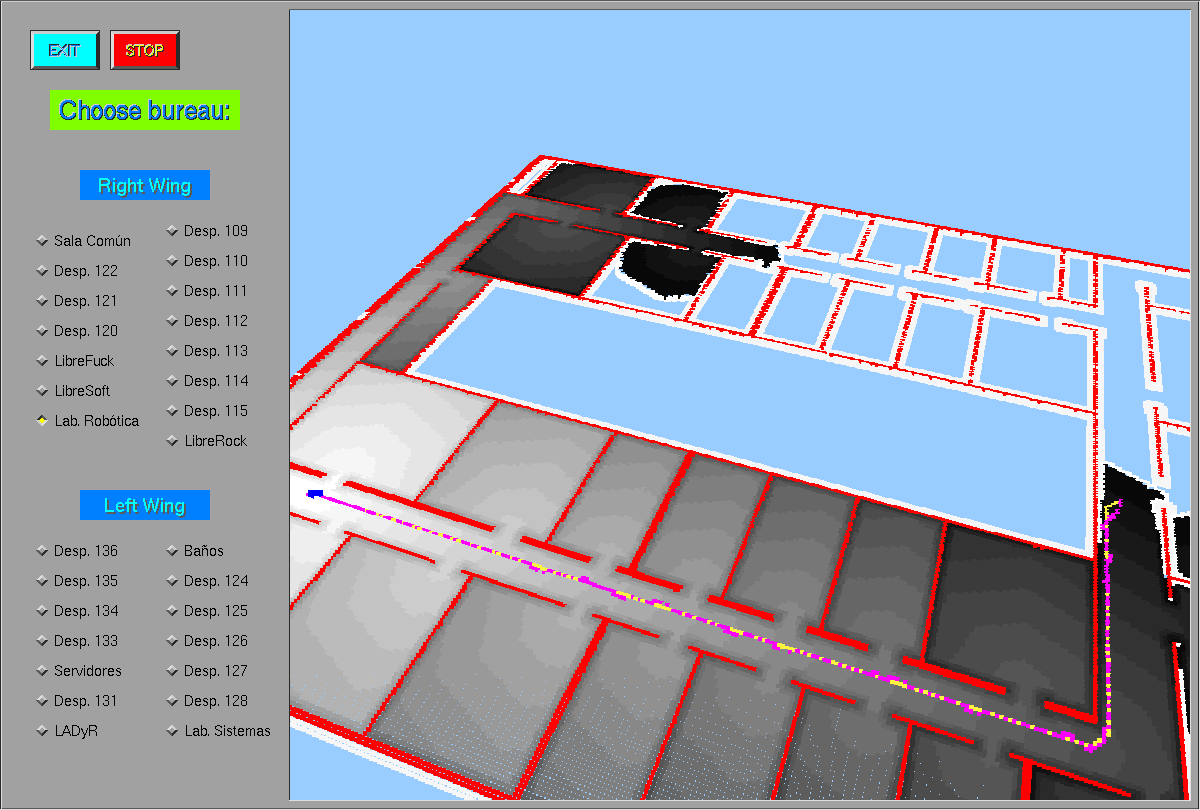
2009.03.30. GlobalNavigation schema draws planned route
Now, when we have just finished to calculate the optimized route between origin and destination, first we draw it on yellow color and then the robot follows it drawing its path on pink color.
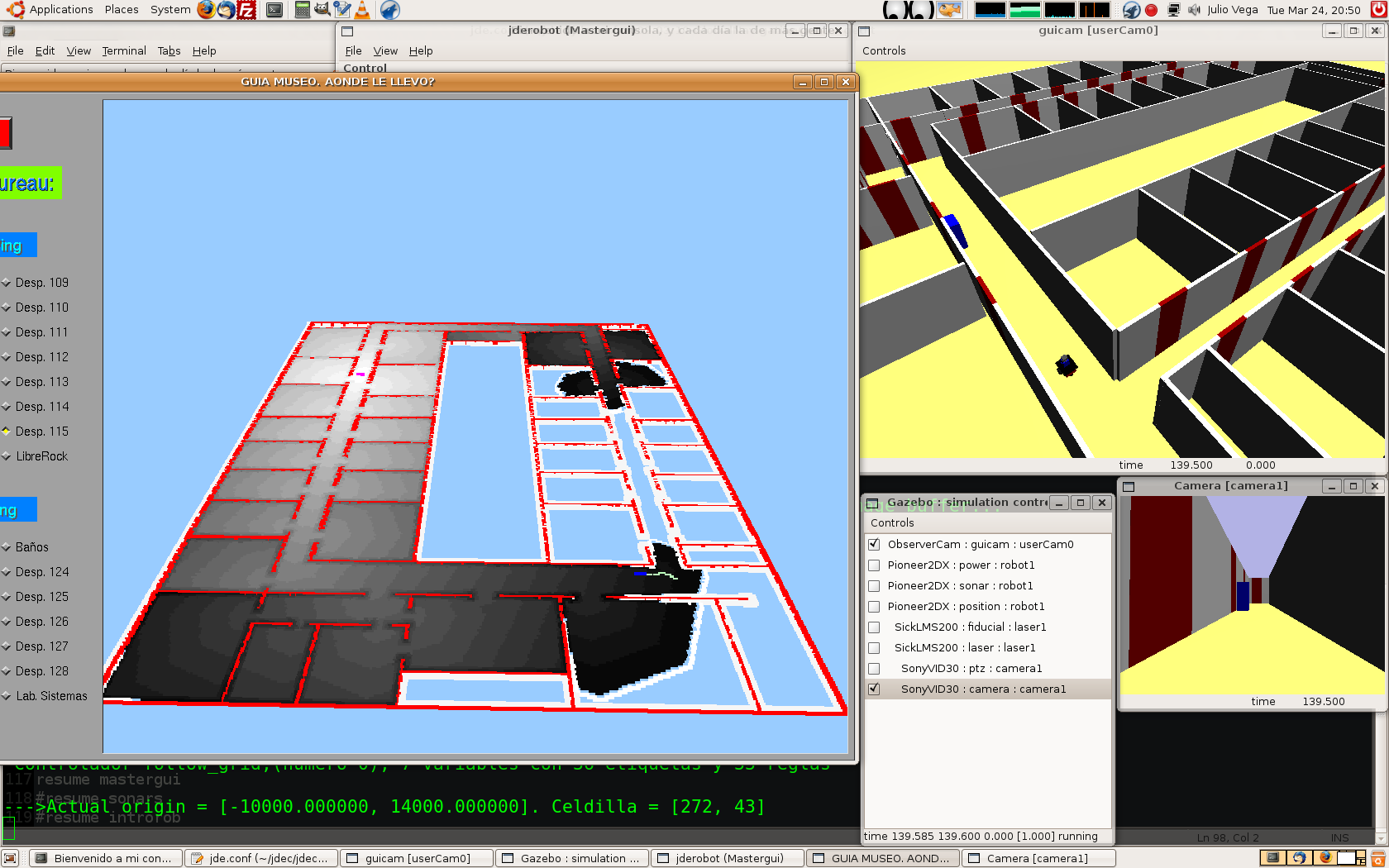
2009.03.29. GlobalNavigation schema with Gazebo simulator
We've been trying to simulate our world with Gazebo. Solved some problems, e.g. initial_position parameter, the simulator works fine and our schema runs as before.
2009.03.28. First stable GlobalNavigation schema
2009.03.27. Border points detected with OpenCV
In order to increase the visual information, we've decided to find image contours, using OpenCV too.
2009.03.27. Frontier points detected with OpenCV
As we told before, now we can detect first border points using OpenCV (without any visual noise).
2009.03.24. Frontera schema using OpenCV
Because of several problems with our proper filter, we've decided to use OpenCV library with Canny Filter. Now the algorithm works fine with lighting changes.
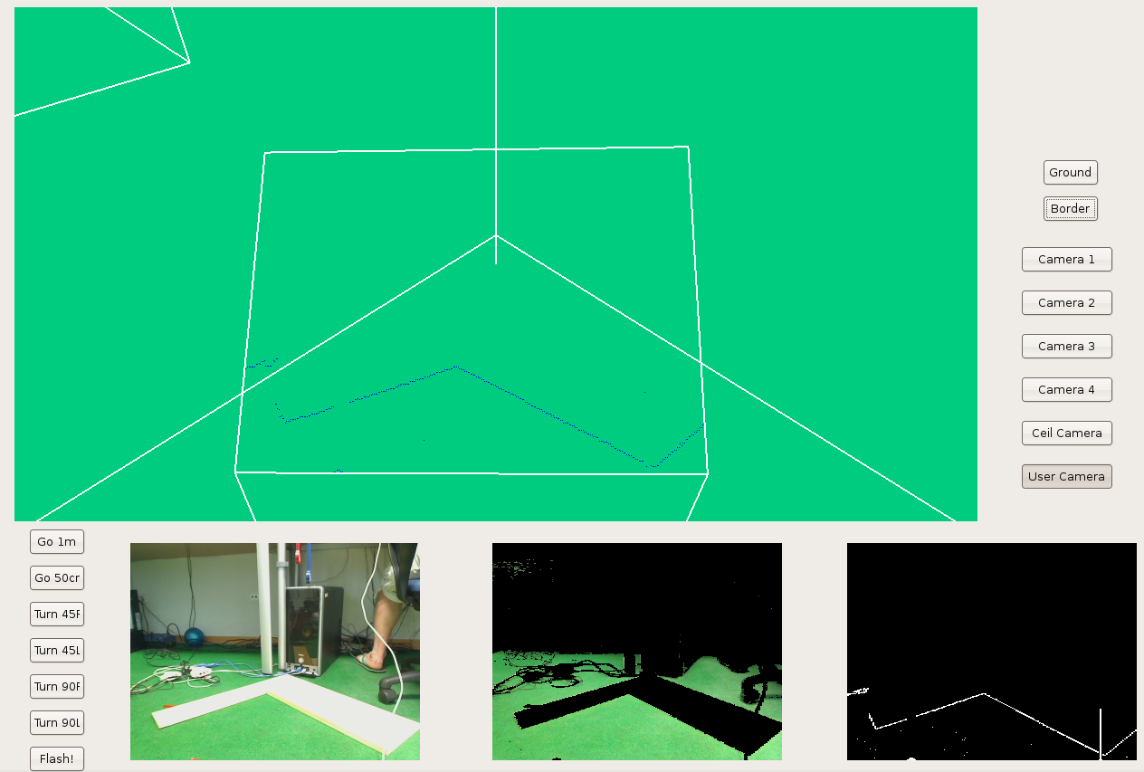
2009.03.20. Frontera schema testing
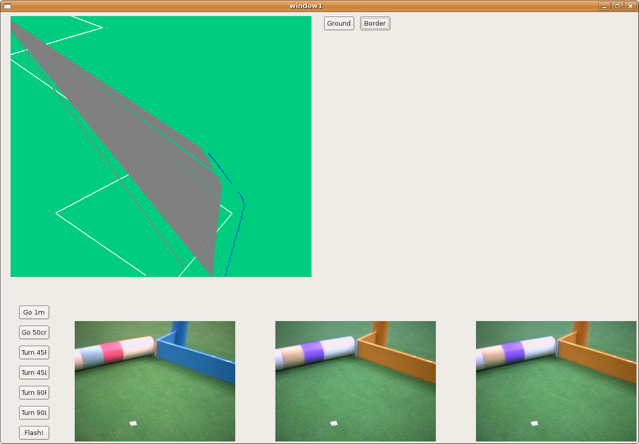
We've been testing several real examples called "Cartabon test". And now we can conclude when objects are too far, our application give us wrong estimated distances.
2009.03.20. Frontera schema includes the virtual Pioneer
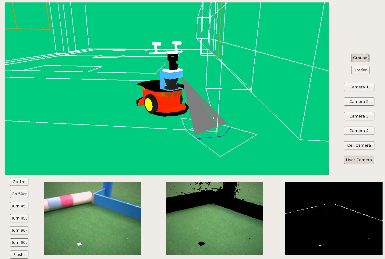
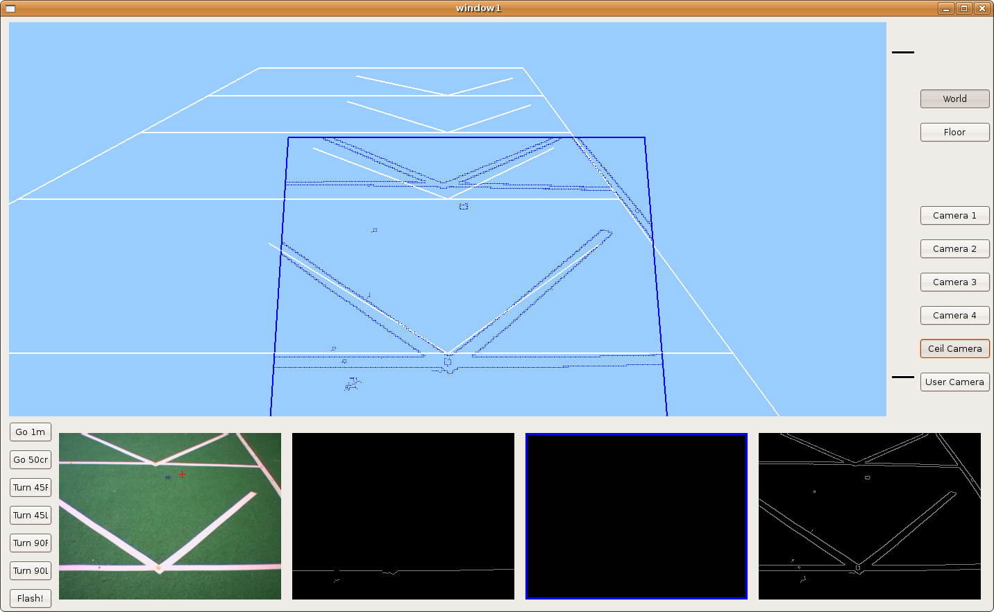
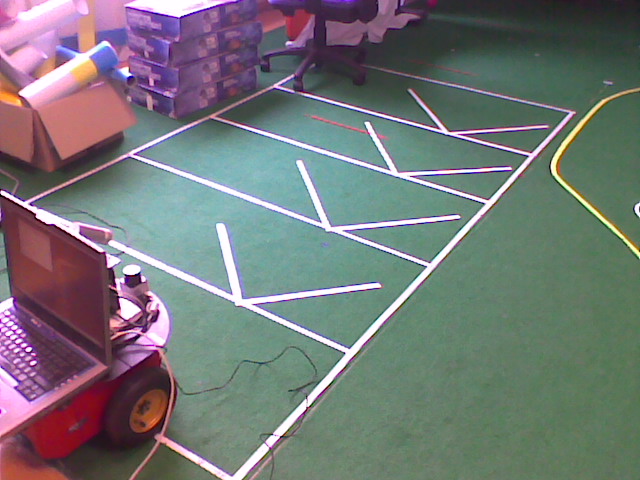
2009.03.10. Frontera schema under GTK
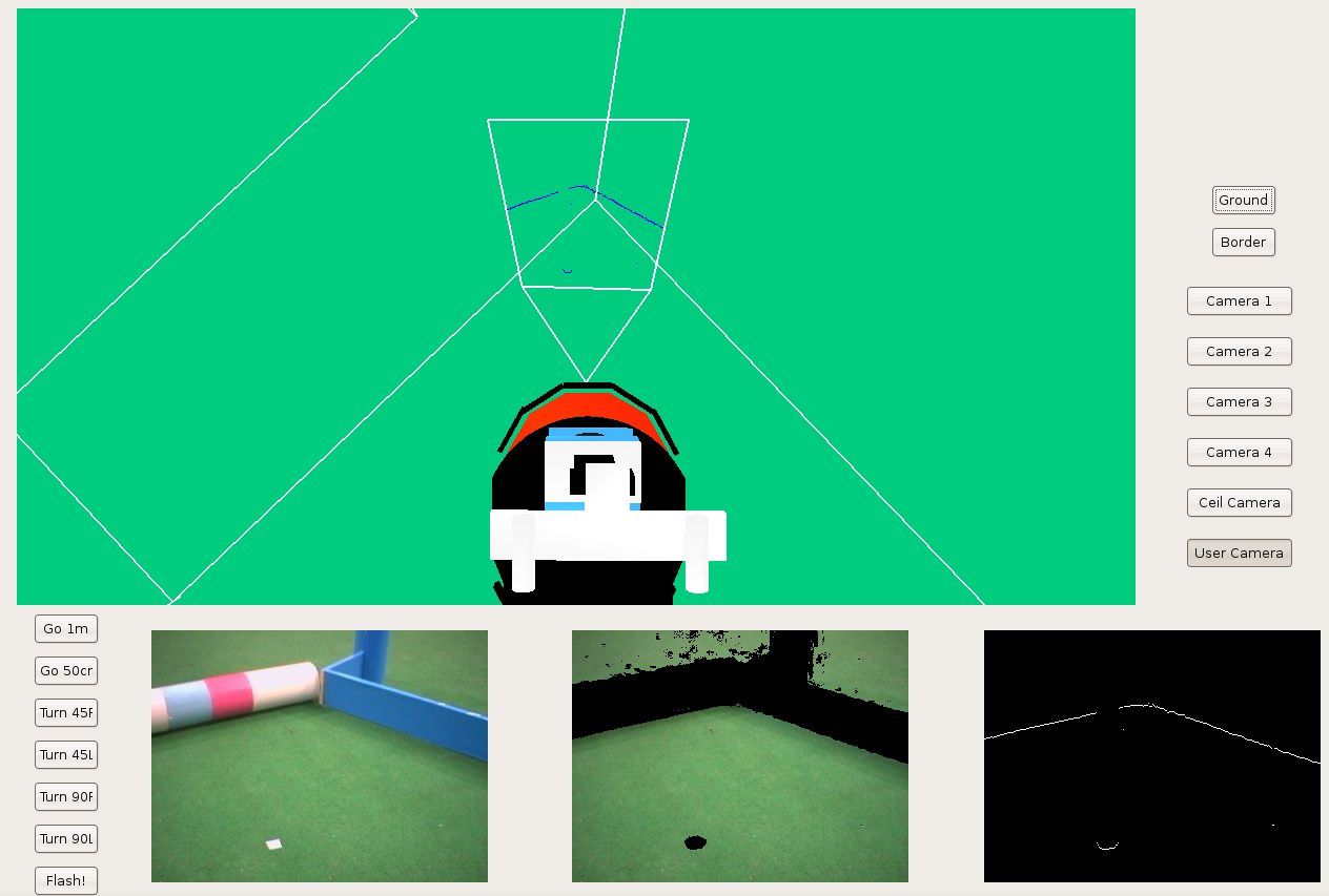
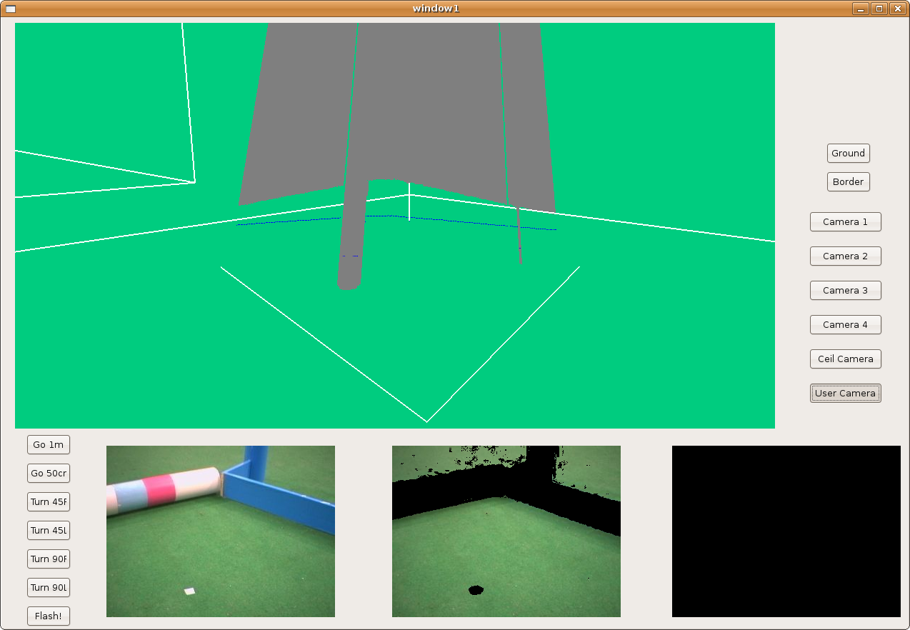
We've developed a new 'frontera' schema interface in order to see the robotics lab scene completely. Now, we've different cameras: 4 lab corner cameras, 1 onto the lab ceiling, and the user camera.
2009.02.24. Frontera schema under GTK
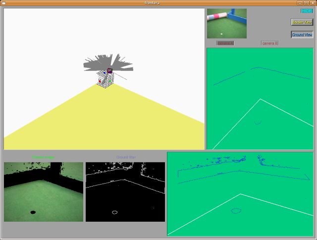
Here we can see the new frontera shema, using GTK. That way we've solved LibXCB problem because GTK has a best multithread control.
2009.02.17. Frontier hypothesis for floor 3D recognition
2009.02.10. Color filtering for frontier hypothesis, from lab ceiling cameras
2009.02.03. Floor 3D recognition using monocular vision from robot camera
2009.01.23. Perlin Noise
Here, I've created a Perlin Noise animation. I usually use Perlin Noise as a procedural texture primitive. That way, I can create effects like this and it's used to increase the appearance of realism in some computer graphics techniques.
For example, on the second image, I've created a virtual landscape using basically Perlin Noise.
2009.01.15. Modeled and animated human skeleton
Here we're a human skeleton laughing. It has been modeled and animated by Maya Software.
2009.01.12. Wandering
With this behavior we want to see the robot moving towards random targets, avoiding all objects that can be in the environment. The wander schema only gives random targets to the local navigation schema through a shared variable called "target". Those targets are calculated with a random C function and are between (0,0) that means the robot position and a max perimeter called "radio".
Also this schema has got a counter. If the target hasn't been reached in "maxtime" seconds, the schema calculates a new target. That way, with this schema the robot is always moving.
Next you have two examples of the wander schema running in Player/Stage simulator and running in a real robot.
The local navigation behavior is quite simple to understand. We use VFF algorithm, already explained. But we've incorporated a new concept called "security window" (you can see it on the next figure). With this device, we can solve some natural situations qualified as "narrow places" (e.g. doors, corridors, ...).
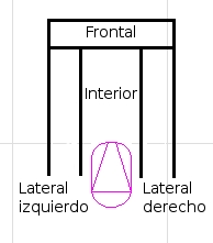
Now, I'm going to explain how it works. Under the followings conditions:
a) There are something over left side, or right side, or both.
b) There are not anything over front of robot position.
...robot can run straight ahead quickly, but null angular velocity!
This functionality is perfectly showed on the previous video, when cleaner-woman goes near to the robot, and it only can run with linear speed. Or when robot goes into WC, and it goes out there.
2009.01.08. Classic pong modeled and animated under Maya
Here we've created a bouncing ball and two strikes. Then, we've animated them; the first part is based on key frame animation, so when we want to describe some movement, we mark the extremes frames as key frames and we design the movement for strikes and ball...